- 您现在的位置:买卖IC网 > Sheet目录980 > G5AU-237P DC5 (Omron Electronics Inc-EMC Div)RELAY GENERAL PURPOSE DPDT 1A 5V
�� �
�
�DISCONTINUED�
�■� Characteristics�
�Type�
�Contact� resistance� (See� note� 2)�
�Operate� (set)� time�
�Release� (reset)� time�
�Operating� frequency� Mechanical�
�Non-latching�
�50� m� Ω� max.�
�5� ms.� max.� (mean� value� approx� 2.4� ms)�
�5� ms.� max.� (mean� value� approx.� 1.1� ms)�
�36,000� operations/hour�
�Latching�
�5� ms.� max.� (mean� value� approx.� 2.0� ms)�
�5� ms.� max.� (mean� value� approx.� 1.8� ms)�
�(max.)�
�Electrical�
�18,000� operations/hour� (under� rated� load)�
�Insulation� resistance� (See� note� 3)�
�1,000� m� Ω� min.� (at� 250� VDC)�
�Dielectric� strength�
�Standard�
�1,000� VAC,� 50/60� Hz� for� 1� minute� between� coil� and� contacts� (See� note� 4)�
�1,000� VAC,� 50/60� Hz� for� 1� minute� between� contacts� of� different� poles� (See� note� 4)�
�500� VAC,� 50/60� Hz� for� 1� minute� between� contacts� of� same� pole� (See� note� 5)�
�Set� and� reset� coils�
�--�
�100� VAC,� 50/60� Hz� for� 1� minute�
�Impulse� Withstand� Voltage� (See� notes� 4� &� 5)� 1,500� V� (10� x� 160� μ� s)� between� contacts� of� the� same� polarity� (conforms� to� FCC� Part� 68)�
�Vibration�
�Shock�
�Mechanical� durability�
�Malfunction� durability�
�Mechanical� durability�
�10� to� 55� Hz;� 1.50� mm� (0.06� in)� double� amplitude�
�10� to� 55� Hz;� 1.50� mm� (0.06� in)� double� amplitude�
�1,000� m/s� 2� (approx.� 100� G)�
�Ambient� temperature�
�Humidity�
�Malfunction� durability�
�300� m/s� 2� (approx.� 30� G�
�-40� to� 70� °� C� (-40� to� 158� °� F)� with� no� icing�
�5%� to� 85%� RH�
�Service� life�
�Mechanical�
�50� million� operations� min.�
�at� 36,000� operations/hour�
�50� million� operations� min.�
�at� 36,000� operations/hour�
�Weight�
�Electrical�
�100,000� operations� min.� (at� 1,800� operations/hr)� See� “Characteristic� Data”�
�Approx.� 3� g� (0.11� oz)�
�Note:� 1.� Data� shown� are� of� initial� value.�
�2.� The� contact� resistance� was� measured� with� 10� mA� at� 1� VDC� with� a� voltage� drop� method�
�3.� The� insulation� resistance� was� measured� with� a� 250-VDC� megohmmeter� applied� to� the� same� parts� as� those� used� for� checking�
�the� dielectric� strength� (except� between� the� set� and� reset� coil).�
�4.� Models� with� FC� suffix:� 1,200� VAC,� 50/60� Hz� for� 1� min,� impulse� withstand� voltage� of� 1,500� V� (10� x� 160� μ� s)�
�5.� Models� with� FC� suffix:� 750� VAC,� 50/60� Hz� for� 1� min,� impulse� withstand� voltage� of� 1,500� V� (10� x� 160� μ� s)�
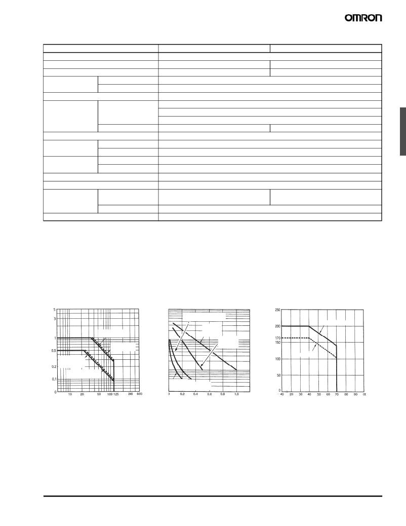
�■� Characteristic� Data�
�Maximum� Switchin� g� Capacity�
�Electrical� Service� Life�
�10,000�
�30-� V� DC� ind� u� cti� v� eload�
�Ambient� Temperature� vs.�
�Maximum� Coil� Volta� g� e�
�5,000�
�(L/R� =� 7� ms)�
�30-� V� DC�
�200� m� W�
�DC� ind� u� cti� v� e�
�DC� resisti� v� e�
�load�
�AC� resisti� v� e�
�load�
�1,000�
�500�
�resisti� v� e�
�load�
�30-� V� AC�
�resisti� v� e�
�load�
�2� 8� 0� m� W�
�load� (L/R� =� 7�
�ms)�
�AC� ind� u� cti� v� e� load�
�(cosf� =� 0.4)�
�100�
�50�
�30-� V� AC� ind� u� cti� v� e�
�load� (cosf� =� 0.4)�
�Rated� operating� v� oltage� (� V� )�
�Rated� operating� c� u� rrent� (A)�
�Am� b� ient� temperat� u� re� (� °� C)�
�Note:� The� maxim� u� m� coil� v� oltage� refers� to�
�the� maxim� u� m� v� al� u� e� in� a� v� arying�
�range� of� operating� po� w� er� v� oltage,�
�not� a� contin� u� o� u� s� v� oltage.�
�Low� Signal� Relay�
�G5A�
�33�
�发布紧急采购,3分钟左右您将得到回复。
相关PDF资料
G5CA-1A-TP-E DC24
RELAY GEN PURPOSE SPST 15A 24V
G5LA-1-E-CF-SP DC12
RELAY GEN PURPOSE SPDT 5A 12V
G5NB-1A-E-SP DC12
RELAY GEN PURPOSE SPST 5A 12V
G5PA-1-WH DC24 BY OMZ
RELAY GEN PURPOSE SPST 5A 24V
G5RL-1-E AC115/120
RELAY GEN PURPOSE SPDT 16A 120V
G5RL-1A DC5
RELAY GEN PURPOSE SPST 12A 5V
G5SB-14-CB DC12
RELAY GEN PURPOSE SPDT 5A 12V
G5SB-14 DC48
RELAY GEN PURPOSE SPDT 5A 48V
相关代理商/技术参数
G5AU237PDC12
制造商:Omron Electronic Components LLC 功能描述:RELAY GEN PURPOSE DPDT 1A 12V
G5AU-237P-DC12
功能描述:低信号继电器 - PCB LOW SIGNAL RELAY
RoHS:否 制造商:NEC 触点形式:2 Form C (DPDT-BM) 触点电流额定值: 线圈电压:5 V 最大开关电流:1 A 线圈电流:1 A 线圈类型:Non-Latching 功耗:140 mW 端接类型:SMT 绝缘: 介入损耗:
G5AU237PDC24
制造商:Omron Electronic Components LLC 功能描述:RELAY GEN PURPOSE DPDT 1A 24V
G5AU-237P-DC24
功能描述:低信号继电器 - PCB LOW SIGNAL RELAY
RoHS:否 制造商:NEC 触点形式:2 Form C (DPDT-BM) 触点电流额定值: 线圈电压:5 V 最大开关电流:1 A 线圈电流:1 A 线圈类型:Non-Latching 功耗:140 mW 端接类型:SMT 绝缘: 介入损耗:
G5AU237PDC5
制造商:Omron Electronic Components LLC 功能描述:RELAY GENERAL PURPOSE DPDT 1A 5V
G5AU-237P-FC
制造商:未知厂家 制造商全称:未知厂家 功能描述:
G5AU-237PH
制造商:未知厂家 制造商全称:未知厂家 功能描述:
G5B01B01012.0
制造商:W L Gore & Associates 功能描述:RF STANDARD CABLE ASSEMBLY